![]()
![]()
Your free Mobile Friendly
Electronics resource.
SELECT YOUR SUBJECT OF INTEREST
FROM THE LIST BELOW, OR
SCROLL DOWN THE PAGE.
.


Your free Mobile Friendly
Electronics resource.
SELECT YOUR SUBJECT OF INTEREST
FROM THE LIST BELOW, OR
SCROLL DOWN THE PAGE. .
You are at the best, free online "Basic Electronics Course". Just read the brief blocks of text, view the videos, and check out some of the screened internet links. This is the easiest, fastest way to learn basic electronics. No sign-up requirements and it is free. The menu table above provides easy access to many interesting electronics topics. Take your time and enjoy.
Everyone today is exposed to electronic devices in one way or another. The computer revolution is a good example. Everyone can benefit from additional knowledge of electronics. Even a quick scanning of this page will help. A study of electronics starts with electricity, magnetism and basic electronics. This includes Ohm's law and other basic principles of electricity. Obtain and study various books on electronics - this is really a must as each author will explain things in a little different way to help you grasp the concepts.
All the internet links to other web sites found on 101science.com were screened to provide you with the BEST the internet has to offer on each subject. This will save you many hours of searching for good educational material. This site is for everyone from the beginner to expert electrical engineering professional. There is something here for every level of expertise in the world of electronics. If you just need information on one specific area, use the table above to navigate to the information you need. If you need more instruction - read on.
Maybe you already know some basic electronics and want to test yourself to see exactly how much you do know.
ELECTRICITY AND MAGNETISM BASICS - It all starts with the electrons moving around atoms. Electricity is the movement of electrical charge from one place to another. Electric charges do not exist without their associated electric and magnetic fields. This module will introduce you to many of the basic concepts involved with electricity and magnetism.
MATTER - Matter is physically everything that exists that we can touch and feel. Matter consists of atoms. Now we will introduce you to the structure of atoms, talk about electrons and static charge, moving charges, voltage, resistance, and current. You will learn about the properties of magnets and how magnets are used to produce electric current and vice versa. All matter can be classified as being either a pure substance or a mixture. Matter can exist as either a solid, liquid, or a gas and can change among these three states of matter. In electronics the most important matter are conductive metals, and non-conductive insulators. In Quantum Field Theory (QFT) you will learn that everything may very well be a field/wave but that is another story for much later in our learning process. Here we will stick to thinking in classical physics terms.
ELECTRICAL CHARGE - Any object or particle is or can become electrically charged. Nobody completely understands what this charge consists of but we do know a lot about how it reacts and behaves. The smallest known charge of electricity is the charge associated with an electron. This charge has been called a "negative" charge. An atoms nucleus has a positive charge. These two un-like charges attract one another. Like charges oppose one another. If you had 6,250,000,000,000,000,000 electrons in a box you would have what has been named; one coulomb of charge. An easier way of thinking about a large number like that is called "powers of ten" and it would look like this 6.25 x 10^18 electrons. It is simply a way to let you know to move the decimal point to the right 18 places. When electrical charges are at rest, meaning they are not moving, we call that static electricity. If charges are in motion we then have a flow of charge called electrical current. We have given the force that causes this current a name called electromotive force and it is measured by a unit called a volt (V). The unit of measurement of the current (I) or movement of the charge is called an ampere. The resistance, or opposition, to current flow is called an ohm (R).
ELECTRICAL FIELDS- Around a charge is an electric field. With every electric field there is a magnetic field. While we can't see these fields, or yet know exactly what they consist of, we can measure them with instruments and tell a great deal about their behavior. We can then use this knowledge to our benefit. The design and construction of electric motors, computers, radios, televisions, stereos, and many other electrical and electronic devices depend upon a knowledge of these basic principles of electricity. As you can see we have given names to these phenomenon to make it easier for us to study and use. We could have called them Dick, Jane and Mary but instead we named them for the scientists that discovered or first studied them; Volt, Ampere, and Ohm. Mr. Volt, Mr. Ampere, and Mr. Ohm spent many years of their lives studying electricity. They were not alone however as many other scientist were studying and learning more about electricity as well.
WATTS - POWER - What is a watt? A watt is the International System unit of power equal to one joule per second. The symbol used for a watt is "P" for power. Power in watts is found by multiplying a circuits current (I) times its voltage (V). You will learn more about power in watts in the ohms law section below.
P - I*V
If you don't have a clue as to what electrical current and voltage are - read on. We will cover that shortly.Moving electric charges are the heart of basic electronics. Knowing what moving charges are and how various electronic components affect the moving charges is the foundation of basic electronics. View the videos and continue on down the page. These are the basic building blocks of understanding "Basic Electronics".
- . -
Now that you have a general background in electricity and moving charges you can move on to learning more about basic electronics. Electronics puts a knowledge of electricity to useful work. Electronics applies electrical current flow of electrical charges to circuits to accomplish specific tasks. Amplifiers can be constructed from glass "tubes" containing metal elements, or more commonly today with solid state diodes, transistors, or integrated circuits. An amplifier is simply a device or circuit that takes a small signal input and controls a larger current as it output. The input signal voltage is small and the output voltage is larger - amplified. A circuit containing wire conductors, resistors, capacitors, inductors and amplifiers can be configured in many ways to build various electronic circuits like oscillators, digital logic circuits, computer circuits, television and video circuits and much more. An oscillator by the way is just an amplifier with some of the output fed back into the input. Sounds like a perpetual motion machine but it isn't as the amplifiers power supply is providing the additional energy that is lost in the circuit and keeps the circulation, i.e. oscillations going.
Basic electronics is all about electrical components and the circuits consisting of those components . Common components are resistors, capacitors, inductors, transistors, and integrated circuits. You will find each of these components described in detail in the following numbered sections. The components are interconnect with conductors, either physical wires or printed circuits. The components make up linear analog amplifiers, oscillators, and filters as examples. They also can be configured to create digital logic circuits such as memories, gates, arithmetic units, and central processing units. So you will find basic electronics in every computer, mp3 player, radio, TV and may other appliances in your home, car, or on your body. Each circuit has a job. Components are interconnected to perform a specific task. First learn about each individual component and how it works then learn about how to interconnect them to make useful end products. Continue your study by reading the numbered sections to follow.
Get the Malvino books below if you need an easy to read but excellent book to learn electronics as a technician.
Instructor's Manual for Malvino...
Experiments for Electronic Principles...
There is another method of learning basic electronics.
It is hands-on by doing simple projects.
You will need some electronic parts avaialbe from a good junk box.
4. RESISTANCE -
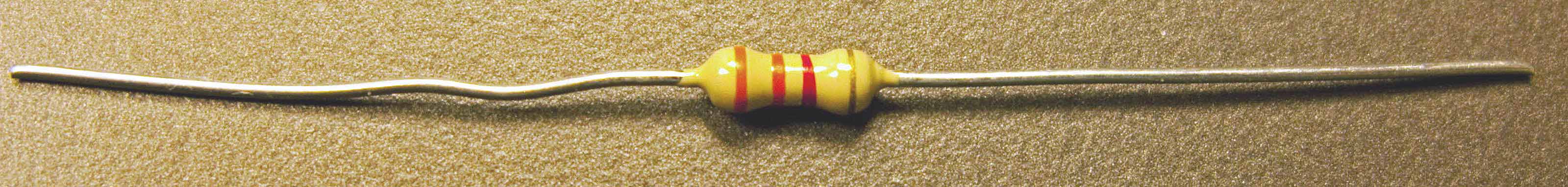
RESISTORS AND RESISTOR CIRCUITS - Resistance is the opposition to current flow in various degrees. The practical unit of resistance is called the ohm. A resistor on one ohm is physically very large but provides only a small resistance to current flow. A resistor of one million ohm's is physically small but presents a high resistance to current flow. A resistance that develops 0.24 calorie of heat when one ampere of current flows through it for one second has one ohm of resistance. The unit of resistance is often represented by the Greek letter omega. Resistors are often made of thin layers of carbon or lengths of small copper wire. They can also be thin deposited layers of metallic material. An image of a few resistor types is shown below.
What is electrical current? Electrical current, represented by the letter "I" in formulas, and it is the flow or rate of electric charge. This flowing electric charge is typically carried by moving electrons in a metallic conductor or electronic components such as resistors or transistors as an example. The unit of electrical current is the ampere, named after a french mathematician, Andre Marie Ampere. What is electrical voltage? Electrical voltage is represented by the letter "V" in formulas and it is the electrical pressure a moving charge is under. In the case of a static charge, one that is not moving, then voltage is the potential difference or pressure of the charge. The relationship between current (I), resistance (R), and voltage (V) is represented by the formulas developed in Ohm's law. We will study that in section 5 below.
RESISTORS AND RESISTOR CIRCUITS-
Resistors can be connected in series (end to end), or in parallel (across one another), or in a combination of series and parallel. If you connect two, 1/4 watt, 100 ohm resistors across one another (i.e. in parallel) then the total resistance in ohms is one half of one of the resistors. In this example the resistance would be 50 ohms. The wattage doubles as the current is now split between the two resistors. The combination can now handle up to one half a watt safely. If the two resistors were connected end-to-end (i.e. in series) the resistances add and in this case would be 200 ohms. The wattage in this series case stays the same, 1/4 watt. This information is handy to know as it is easy to calculate in your head and will allow you to devise additional resister values from a limited resistor bench stock. Resistor color code calculator.
RESISTORS IN SERIES: Connecting resistors in a string one pigtail to another is called connecting them in series. When connected this way the resistance of one resistor adds to the next in line. For example a 100 ohm resistor in series with a 500 ohm resistor is the same as having a 600 ohm resistor. The wattage capability stays the same, in other words if the resistors are all 1/4 watt the string is 1/4 watt.
Resistance in series resistance simply adds: R = R1 + R2. This can be extended for more resistors: R = R1 + R2 + R3 + R4 + ...
RESISTORS IN PARALLEL: When resistors are connected in parallel (parallel; meaning they are tied across one another) their combined resistance is less than any of the individual resistances. There is a special equation for the combined resistance of two resistors R1 and R2:
Combined resistance of
two resistors in parallel:R =
R1 × R2
R1 + R2
For more than two resistors connected in parallel a more difficult equation must be used. This adds up the reciprocal ("one over") of each resistance to give the reciprocal of the combined resistance, R:
1
=
1
+
1
+
1
+ ...
R
R1
R2
R3
The simpler equation for two resistors in parallel is much easier to use!
Note that the combined resistance in parallel will always be less than any of the individual resistances.
Resistor values are measured in ohms. A thousand ohms is written as 1k to eliminate all the zeros. The k represents three zeros. A million ohms is represented by 1M. Therefore; 1000 ohms = 1k ohm and 1000k ohms = 1M ohm. Since resistors are so small their value is marked by a color code.
RESISTOR COLOR CODES - Resistors use color coded stripes to indicate their value in ohms. 0=Black, 1=Brown, 2=Red, 3=Orange, 4=Yellow, 5=Green, 6=Blue, 7=Purple, 8=Gray, 9=White.
|
Video showing resistor color codes.
5. OHMS LAW
Ohm's Law is extremely important in learning basic electronics.
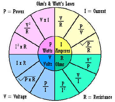
What is Ohm's Law? Ohm's Law is a formula that describes the relationship between resistance, current and voltage in an electrical circuit. The formula is R (resistance in ohms) = (equals) V (voltage in volts) divided by I (current in amperes).
That is: R = V ÷ I
...and algebraic rules tells us that I - V ÷ R and V = I*R.
I = V ÷ R, V = I*R, R = V ÷ I, and P (power in watts) = I*V are the fundamental formulas of Ohm's law. (The * means to multiply the two quantities together). Where V is the circuit voltage in volts, I is the circuits amperage in amps, and R is the resistance in ohms.
Almost every electrical and electronic circuit involves resistance, current and voltage. This is why it is vital you understand the relationships between them.
As an experiment you can set up a circuit by connecting resistors in series with a battery, measure the voltage across the resistors with a voltmeter, measure the current in the circuit by placing an ammeter in series with the resistors and the battery. If you know the voltages and current in the circuit you can use Ohms law to calculate the resistance. With the resistor out of the circuit you can measure it's resistance directly with an ohm meter. The multi-meters today can measure ohms, volts and amperes (usually measured in miliamperes in practical circuits) all in one piece of test equipment.
Below is a graphic chart showing the various relationships between resistance, current, voltage, and power and shows how one unknown can be calculated if you know the other two.
6. CAPACITORS -
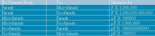
A capacitor is a device that stores an electrical charge when a potential difference (voltage) exists between two conductors which are usually two plates separated by a dielectric material (an insulating material like air, paper, or special chemicals between two sheets of aluminum foil). Capacitors block DC voltages and pass AC voltages. They are used as filters, AC coupling capacitors and as by-pass capacitors. They are also used in conjunction with resistors and inductors to form tuned circuits and timing circuits. A capacitors value C (in Farads) is dependent upon the ratio of the charge Q (in Coulombs) divided by the V (in volts). Common capacitors come in values of microfarads or Pico farads. Often you will have to convert between Pico farads and micro farads. A chart is provided below to assist in the conversion. For a list of capacitor terms defined: Click HERE. Measuring capacitance requires a capacitance meter. This is separate piece of test equipment. There are attachments for multimeters that allow measurement of capacitance directly. Also read this tutorial on how to test capacitors.
CAPACITOR Value Conversions:
Some capacitors may be marked in micro farads and others of the same capacitance value marked in Pico farads. One Pico farad equals one micro-micro farad. You may need to make conversions between the two equivalents.
Prefix
Power of 10
Example
Mili
10^-3
.001
Micro
10^-6
.000001
Nano
10^-9
.000000001
Pico
10^-12
.000000000001
1 micro F = 1000000 uuf 1 uuf = 1 pf .01 uf = 10000 pf .005 uf = 5000 pf .009 uf = 9000 pf .0001 uf = 100 pf .0005 uf = 500 pf .0009 uf = 900 pf A capacitor marked 104M is a .001 uf +- 20%
A capacitor marked 103M is a .01 uf +- 20%
A capacitor marked 102M is a .1 uf +- 20%
Capacitance and capacitors - watch the video.
Take a break and please support 101science.com with your purchase of Amazon.com items below.
While this web site provides a quick background in basic electronics totally free
you need additional supporting books to reinforce and obtain in-depth details.
Reading, and studying and having books for reference is your main path
to a solid foundation in basic electronics and electrical engineering.
Your support is appreciated. Thank you!Get an Arduino Starter kit to learn hands on about electronics and microcontrollers.
Now continue below with your free "basic electronics" learning process.
Yes, it is that easy!
7. INDUCTORS -
Inductors are usually made with coils of wire. The wire coils are wound around iron cores, ferrite cores, or other materials except in the case of an air core inductor where there is no core other than air. The inductor stores electrical charge in magnetic fields. When the magnetic field collapses it induces an electrical charge back into the wire. Inductors are associated with circuit capacitance and can form a tuned circuit and resonate at a particular frequency. Two coils close to one another, as they are in a transformer, literally transfer charge from one coil to the other. This is called mutual inductance.
Inductor Calculators:
Inductance Calculator
Circuit Sage: Inductor Tools and Links
The Engineers' Club Online Service - Engineering CalculatorsFERRITE CORE TOROIDS - a special type of inductor
Today you must learn about powdered iron cores and ferrite materials for winding your own toroidal coils. Click here for basic background information on powdered iron and ferrite materials. You will need to know the formulas for calculating toroidal core inductors; click HERE for FORMULAS. The cores will be made from different materials. You will also need information on powdered iron material. Now you have all the information you need to wind toroidal coils for your electronics projects. For core material table: https://www.amidoncorp.com/pages/specifications
To calculate the approximate inductance of a toroid, use the JAVA calculator found here: http://hyperphysics.phy-astr.gsu.edu/hbase/magnetic/indtor.html#c1 Courtesy of Carl R. (Rod) Nave, Georgia State University. Be sure to visit their main site loaded with JAVA calculators and other science information at: HyperPhysics http://hyperphysics.phy-astr.gsu.edu/hbase/hph.html including an offer of a CD containing of all their fine materials.
Toroid Approximate Inductance CALCULATOR - Toroid CALCULATOR
Torroid Inductance charts: http://www.electronics-tutorials.com/basics/toroidcharts_mcq.htm
http://home.sandiego.edu/~ekim/otherjunk/inductor.pdf
Testing Unknown Ferrite Cores
Ferrites are roughly divided into two groups. Those with permeabilities up to 850 are usually made from nickel-zinc material and have high volume resistivity ranging from 1x10⁵ to 1x10⁸. Higher permeability ferrites are usually made from manganese-zinc material and have volume resistivity ranging from 0.1x10² to 1x10². Iron powder cores are usually color coded and have very high volume resistivity. An initial test of the material can be made by checking the dc resistance between opposite faces/sides of a core. Low readings indicate a high permeability material. If you can measure inductance at a low frequency (10-100kHz), wind 10 turns of wire on the core and measure the inductance. You can then work back from the ferrite material formula and calculate the AL value, which can be compared with the tables of known cores of the same physical dimensions and so come up with a reasonable match. If 10 turns does not give a measurable reading try 20 or 30 turns.
RF power rating can be roughly checked by using two exactly similar cores each wound with the same primary and secondary turns (say 10 turns each on primary and secondary) and then connecting the cores back to back as shown. This arrangement provides a 1:1 equivalent so that the transmitter sees the correct load. Losses are doubled by using two transformers, but this does not matter for the test. Set the transmitter to the desired frequency and reduce the rf power output to a minimum. Increase the power output in small steps (say 5 -10W per step) holding each setting for 30 seconds then checking the temperature of each transformer. The transformers should only get warm to touch but NEVER hot. When the final temperature of each transformer has reached about 40 deg.C you can say that you have reached the power limit for that particular core. Some cores will get hot at very low power. You have to make a value judgment about the core physical size versus the power rating achieved.
Ferrite (software program) is used to calculate the number of turns required on toroidal ferrite cores to achieve the desired millihenry-value inductance. 15 different ferrite toroids are included in this application. This program will calculate the winding data for an inductance range of 0.001 to 27 millihenries.
Style: CONSOLE , File size: 64K , zipped 31K.
Bug Fixes: Thanks to PA3CKR for the bug report ; fixed Jan 19/99.
Current Version is 1/19/99
Download the ferrite.zip file
RESONANT CIRCUITS - a combination of capacitance, inductance and resistance.
Tuned circuits are found within electronic circuits where, for example, only one certain frequency is of interest. The filtering action of a tuned circuit is often associated with amplifiers as is found in a radios intermediate frequency stage. Only one frequency is amplified due to the filtering action of the tuned circuit. Tuned circuits may be designed for a very a narrow band of frequencies or with a wide bandwidth. Tuned circuits are also found in oscillators. Here the tuned circuit allows oscillations only at the tuned circuits resonant frequency in a properly designed circuit. Resonant circuits are a combination of inductance, capacitance and resistance. Please look at some of the links below for more detailed study of resonant circuits..
Links to other interesting web site about toroids and other inductors.
Useful hints concerning winding toroid coils.
Building a toroid http://www.hamradio-online.com/1999/apr/w6bky-10.html
Toroid Inductance Charts http://www.electronics-tutorials.com/basics/toroidcharts_mcq.htm
A GREAT Inductor Impedance CALCULATOR online - http://www.cvs1.uklinux.net/cgi-bin/calculators/ind_imp.cgi
- Introduction - Use of Ferromagnetic Cores
- Choice of core material - choice of material is of prime importance
- What size toroid core? - Design examples are given
- Using the data tables
- Winding hints
- Line filters and chokes
- Switched mode supplies
- Variable coil forms
- Suppression beads
- Bobbin core
- Balun cores
- Core cross references
- Downloads
- RFI suggestions
- Magnetic formula
- Australian resellers
- Price lists
- Ordering information
- Links
A Video Demonstrating a Resonant Circuit
Links to other interesting web sites about resonant circuits.
Resonant Circuits Link
Resonant Circuit Formulas
More Resonant Circuit Information resonance
Resonant circuits
RLC Circuits - Introduction
What is the formula for resonance in a series and parallel circuit ...
Get more discussion results
Rlc Circuit Formula | Best Of Web | TutorVista
Lessons In Electric Circuits -- Volume II (AC) - Chapter 6
Resonance
[PDF] Sophomore
Physics Laboratory Analog Electronics: Resonant Circuits
[PDF] ELEC290:
Linear Circuits (Electronics II)
Electronics
38
RESONANT
CIRCUITS AS FILTER CIRCUITS
CASPOC
- Power Electronics Simulation Software
Resonance
in series-parallel circuits - Chapter 6: RESONANCE
Electronics
Technician - Program Outline
Electronics
- T
Interactive
Power Electronics Seminar (iPES)
Also
see, ALL ABOUT CIRCUITS: http://www.allaboutcircuits.com/vol_2/chpt_9/1.html
Electrical
Circuit Theorems - EngPlanet.com: Library of Electrical
Circuit Theorems http://www.engplanet.com/redirect.html?1900
Parallel
Resonant Circuits
Resonant Circuits I
Resonant
Circuits II
resonance
RESONANT
CIRCUITS III
RESONANT
CIRCUITS AS FILTER CIRCUITS
[PDF] Resonant
Circuits by Time and Frequency
[PDF] Sophomore
Physics Laboratory Analog Electronics: Resonant Circuits
Resonant
Circuits in a Magnetron Tube
A
Composite Capacitor/Inductor Assembly for Resonant Circuits
GREAT Tuned Circuit Impedance CALCULATOR online - http://www.cvs1.uklinux.net/cgi-bin/calculators/tuned_circuit.cgi
Software concerning Inductors
| CaMF1.zip | 51k | LP or HP filter and matching circuit calculation. See notes on CaMF |
| CaLC3.zip | 46k | General impedance calculations, LC circuits calculations. Textfile describes, how to use it. |
| CaNI1.zip | 41k | RX front-end IMD and noise figure calculations |
| CaIT1.zip | 48k | Toroidal coil calculations |
| CaIW1.zip | 45k | Wire coil calculations |
| CaQI1.zip | 39k | Inductance and Q measurement helper program |
| Ca2LQ1.zip | 42k | Inductance and Q measurement for coils with parasitic capacitance |
| CaXtal1.zip | 44k | Quarz crystal calculator. It calculates equivalent circuit values from a measurement in a 50 ohm line |
| CaRA1.zip | 44k | Resistive attenuator calculations |
| Xline1.zip | 49k | Microstrip stub design, general tapered stub with reactive termination |
| Tline2.zip | 54k | Impedance transform in a transmission line with microstrip calculations |
Do you need math skills to understand electronics? Yes! All science subjects including electronics (a division of physics) require various levels of understanding mathematics. If you are interested in electronics only as a hobby then general math may be all you will need, to get by. If you are serious about becoming an electronic technician then you will need at least a basic understanding of algebra and and be able to use and make graphs. Electrical engineers need advanced mathematics training through calculus.
Why, you may ask? Basic electronics involves the use of equations. For example, Ohms law requires a basic knowledge of algebra to fully understand it and to be able to use it effectively. Electronic technicians will use Ohms law and other algebraic formulas frequently in typical day's work. Some knowledge of trigonometry would be helpful. Electrical engineers need to know how to calculate various rates of change in electrical parameters in a quick and relatively simple manner. Without the appropriate skills at your level of interest you will be greatly handicapped in your work. There are substitutes for many situations such as pre-printed charts, databases, cookbook circuits, and internet resources. But they may not quite serve your current purpose and will take time to research and find. It is best to obtain basic math skills to a level required by your specific work.
- Learn algebra here.
- Learn about graphs here.
- Learn about graphs of a line here.
Learn about graphing a function here.- Learn more about domain and range here.
- Learn about geometry HERE.
- Learn about statistics for electronics HERE
- Learn about trigonometry here.
- Learn calculus here. (Don't miss this - click)
- Learn about using MathCad for electronics problems.
- See our mathematics section for more math links.
Scared of calculus? Scared of calculus symbols? No need to be as they are not meant to scare you. They are really very simple once you know how to think about them and know what they represent. For example, often you will see the symbol d or perhaps dx in a formula. Well, d simply means a small amount of something. So, dx simply means a small amount of whatever x represents. Don't try to multiply the two (d and x), they are not meant for that, just think of dx as a small amount of x, period. The symbol dx is called a differential. Also, you might have seen this symbol,
called an integral. Now that is scary, right? No, not any more because now you know it is simply a tall skinny S. Now how can a tall skinny S scare anyone? If you think of
So how does calculus help us in electronics? The whole purpose of calculus is to make very difficult calculations easier. Yes, sometimes down right easy or usually at least somewhat easier. Most people think calculus is designed to make simple calculations difficult to impossible. But that is only because they really don't speak or understand calculus. It is sort of a foreign language. Learn to understand the language like we did above and calculus gets a lot easier. One example is calculating a transformer rate of change in output voltage at any one given instant. A much easier problem to solve if you use calculus. Who dreamed this calculus stuff up any way? If you want to read about the history of calculus go HERE. If you want another clear explanation of calculus read this - HERE.
| Algebra
& Geometry |
Linear
Alg. & Matrices |
Trig.
& Vectors |
Logs
& Exponents |
Differential Calculus | Integral Calculus | Differential Equations |
| go to topic | go to topic | go to topic | go to topic | go to topic | go to topic | go to topic |
Definitions of electrical engineering on the Web:
See some examples of differential calculus and how it it used in electronics HERE.
Understanding CapacitanceInductance Formulas - Science Forums and Debate
A function is something whereby you can put in some variable and get a different, dependant variable out. So, if f(x)=2x-3, you can put in some value, say 6, and get f(6)=2(6)-3=9.
Differentiation of a function is the generation of another function for which the "y-value" (value of the dependant variable at a given "x-value," or independant variable) of the second is equal to the gradient, or slope, of the first.
For example, take the function y=f(x)=x^2. For any given x, there is a y that is equal to x^2. The derivative of this function happens to be f1(x)=2x, meaning that for a given point on the original curve, its slope can be represented by 2x. So, at x=4, f(x)=4^2=16, and its slope at that point, f1(x)=2(4)=8, or 8 units up for every 1 unit over.
The dy/dx means instantaneous change in y divided by instantaneous change in x. An explanation: Slope is measured by change in y divided by change in x. So between two points on a curve, the y-value of the second minus the y -value of the first, all divided by the x-value of the second divided by the x-value of the first, will give you the slope of the straight line between those two points, also called the secant. But we want the slope at a point, which poses some problems. How can there be any change at one point? Well, there can't, really, but what we can do is find the change between two points which are closer to one another than any finite distance. We can determine through algebra that as you make the distance between them smaller and smaller, the change in y over change in x gets closer and closer to some definite ratio, which is the "limit" as the distance between them "approaches zero." Thus, the "dy/dx" is that ratio at an infinitely small distance, thereby effectively being the slope at one point.Understanding CapacitanceInductance Formulas - Science Forums and DebateIf it's an upper case sigma then that means the sum of a sequence.
It's got everything to do with integrals. An integral is the sum of the rectangles under the curve, change in x (width) times height, the change in width approaches zero and the number of rectangles approaches infinity. Sums are where integrals come from. It's basically "the sum of all y-values."
Understanding CapacitanceInductance Formulas - Science Forums and Debate
For AC electronics, designing circuits is easily done, using complex numbers.
Imagine a voltage source with a angular frequency ω and amplitude A, so as function of time you have V(t) = A*cos(ωt).
Now, replace this with a voltage X(t) = A*exp(ωt). Now, the real voltage can be written as the real part of X(t), being Re(X(t)) = A*cos(ωt).
Using this formalism, you can treat every passive linear component as a complex resistor Z. For lumped devices there are basically three types:
Capacitor with capacity C: Z = 1/jωC
Resistor with resistance R: Z = R
Inductor with inductance L: Z = jωL
Here the number j has the property j² = -1.
Now I'll give an example with three nodes, GND, VIN, VOUT. Between GND and VIN there is a voltage source X(t). Between VIN and VOUT there is a resistor R. Between VOUT and GND is a capacitor C. What is the output voltage as function of input voltage?
This now can be easily solved. We introduce a complex voltage XOUT and XIN.
We have a series connection of two resistors. Using basic circuitry for resistors you find
XOUT = XIN * (ZC / (ZC + ZR)), where ZC is the capacitor's complex resistance and ZR is the resistor's complex resistance.
Now XOUT = XIN *(1/jωC) / (R + (1/jωC)) = XIN / (1 + jωRC)
So, you have XOUT as function of XIN and the angular frequency ω.
The amplification as function of frequency ω can be written as 1/sqrt(1+ω²R²C²). There also is a phase shift, between input and output. That is -arg(1 + jωRC). For small ω (close to DC), the phase shift is close to 0, for high ω, the phase shift is almost 90 degrees.
If you understand complex numbers, then this should be easy to grasp, otherwise it indeed will be very difficult for you to determine transfer functions of capacitive and inductive circuits.
THIS IS GREAT FREE ELECTRICAL ENGINEERING INFORMATION!
For Electrical Engineering - QuicKTime Movie - Review of Pre-Calculus Math -
http://www.anselm.edu/internet/physics/cbphysics/downloadsI/MathSkillsVideo.html
Great Calculus Tutorial to get you started http://www,math.hcm.edu/calculus/tutorials/substitution
Free eBook - Calculus Based Physics I
Copyright 2005-2008, Jeffrey W. Schnick, Creative Commons Attribution Share-Alike License 3.0. You can copy, modify, and rerelease this work under the same license provided you give attribution to the author. See http://creativecommons.org/
http://www.anselm.edu/internet/physics/cbphysics/downloadsI/cbPhysicsIa18.pdf
Free eBook - Calculus Based Physics II
http://www.anselm.edu/internet/physics/cbphysics/downloadsII.html
Download Mathematics & Simulation / Mathcad from Adept Scientific ...
Ashley - Analog Electronics with LabVIEW
EE 3050 - Analog Electronics
EDN - MathCAD functions perform log interpolation
[PDF] Chart Analysis Enhanced with Mathcad
http://www.benkoltd.com/yazilim/mathcad/Mathcad_Files.htm
Mathcad files for electronics http://www.mathcad.com/resources/search/search_results.asp?t=electronics&tp=000000
Mathcad Circuits http://www.mathcad.com/library/LibraryContent/MathML/Ashley.htmMathcad Resources for Electronics - Circuit Sage
Home
New Routine
A/D Design
Filter Design
Impedance Matching
Inductor Design
LNA/PA Design
PLL Design
Transceiver Design
Transmission Line Design
The following MathCad scripts accompany the book
"High-Speed Signal Propagation: Advanced Black Magic"
These scripts may be used to simulate long transmission structures using the frequency-domain method, which for linear systems is acknowledged as the "gold standard" against which other simulation technologies are measured. These scripts provide incredible control over every parameter of simulation. They may be re-programmed to suit almost any need. The scripts are provided in MathCad syntax, and also in the form of .pdf files in case you want to just see the equations so you can port them to another brand of mathematical spreadsheet.
Please go to the separate TRANSISTOR page Click >> HERE
Transistors and amplification introductory - basic information. http://landau1.phys.virginia.edu/classes/241L/transist/transold.htm
NEW! Click HERE for the latest breaking Semiconductor Industry News.
Radio Calculators http://www.qsl.net/yo5ofh/data_sheets/amateur%20radio%20computer.htm
Semi-conductor DATA SHEETS http://www.qsl.net/yo5ofh/data_sheets/data_sheets_page.htm
Magnetron Tutorial http://www.gallawa.com/microtech/magnetron.html
Digital electronics is based on electronic switches. A circuit is either on or off represented by the presence of a voltage or not or in some cases two different voltages. A string of on or off conditions are made to represent numbers. These are usually binary numbers but could be based on a variety of mathematical bases. For example, "Hexadecimal" or a base of 16. But the most common is binary. Any number can be represented in a binary based system with a series of ones' and zero's (voltage on/off conditions). Here is a short table of some binary numbers and their decimal equivalents. The binary numbers place values from right to left as shown in the table are; one, two, four, and eight. So, binary 1111 is the same as adding 1+2+4+8 from right to left and that equals 15. See the samples below then study the chart.
1 1 1 1 = 15 binary 1 0 0 1 = 9 binary 1 0 1 1 = 11 binary
8+4+2+1 = 15 decimal 8+0+0+1 = 9 decimal 8+0+2+1 = 11 decimal
DECIMAL= |
BINARY |
DECIMAL = |
BINARY |
0 |
0000 |
8 |
1000 |
1 |
0001 |
9 |
1001 |
2 |
0010 |
10 |
1010 |
3 |
0011 |
11 |
1011 |
4 |
0100 |
12 |
1100 |
5 |
0101 |
13 |
1101 |
6 |
0110 |
14 |
1110 |
7 |
0111 |
15 |
1111 |
For an online course on digital electronics and how binary mathematics is used in LOGIC blocks visit this web site: http://www.gamezero.com/team-0/articles/math_magic/micro/comb.html
Digital Projects: http://www.eleinmec.com/category.asp?3
These basic concepts are the building blocks for more sophisticated configurations of digital electronic integrated circuits. Today digital integrated circuits combine hundreds and thousands of switches per IC package. It is not necessary to know exactly what the internal circuitry is but you must know the fundamentals to understand how to use the IC's together to build digital equipment. Our computer industry today depends upon many people knowing and using these same basic fundamentals.
The free MultiMedia Logic software is available at http://www.softronix.com/logic.html
Download the "Setup Kit".
IMPORTANT: Be sure to check out all the links in the table below. Some very good information there.
(15)TTL Logic |
(16)Eddy Currents |
Digital Electronics Online Problem - http://science-ebooks.com/electronics/digital_electronics.htmDigital Electronics & Superconductors http://www.ece.rochester.edu/~sde/cool/coollinks.html
Howstuffworks "How Electronic Gates Work"
Digital Electronics Corporation
Digital Electronics II
Digital Logic
TTL Logic
COMOS DATASHEETS
http://www.electronics-lab.com/downloads/datasheets/cmos.html
TTL DATASHEETS
http://www.electronics-lab.com/downloads/datasheets/ttl.html
More at http://www.electronics-lab.com/downloads/index.htmlDigital Logic and Computer Systems College Course http://www.physics.mcmaster.ca/phy4d6/
McMaster University, Hamilton, Ontario, Canada.Digital electronics Book recommendation: Digital Systems,
by by Ronald J. Tocci (Author), Neal S. Widmer (Author)
Television Tutorials - Williamson Labs!
1_
2_
3_
4_
5_
6_
Color Encoding: Color Bars, Camera,
RGB, YIQ, Color Subcarrier7_
8_
Digital TV/Graphics: ADC-DAC, Frame Buffers, Timebase Correction, VGA
9_
10_
EIA 1956 Video Resolution Chart for printing
http://www.bealecorner.com/trv900/respat/EIA1956.pdf
Television means "seeing at a distance". It may be described as a system for the conversion of light rays from still or moving scenes and pictures into electric signals for transmission or storage, and subsequent reconversion into visual images on a screen.
Basically the image formed by the camera lens is focused on a light sensitive material that is scanned in horizontal lines with each line following closely beneath it. The light intensity (and color) is converted into an electrical signal and transmitted over the air or through cables to a receiver. The "TV" receiver converts the electrical signals back into scan lines traced on a cathode ray tube (CRT). The fluorescent material on the face of the CRT is activated by the CRT's scanning electron beam to re-form the picture.
Basic Video information HERE. http://webs.soltec.net/movpic/Video.htm
NTSC signal information: http://www.seanet.com/Users/bradford/ntscvideo.html
Free television and video articles and guides HERE. http://www.videouniversity.com/article2.htmClick HERE to view a "large list" of links related to television and video.
Electronics Tutorials - Williamson Labs!
Graphing
No matter what program you have to help you, everyone needs to understand why we produce graphs, and how to interpret them properly. Here's a basic guide, including paper to print out!
- Log Graphs - essential for A-level candidates!
- FREE Graph Paper! - all popular metric sizes!
NEWS! Click on titles below for the latest breaking news - updated every 15 minutes."AT&T Corporation" NEWS.
"Computer Security" NEWS.
"Computer Services" NEWS.
"Consumer Electronics" NEWS.
"Digital Television" NEWS.
"Engineering" NEWS.
"Handhelds" NEWS.
"Hewlett Packard" NEWS.
"IP and Patents" NEWS
"Microsoft" NEWS
"PC Industry" NEWS
"PC Software" NEWS
"Personal Technology" NEWS
Antenna wavelength calculator
Enter operating frequency and then click the full wavelength (WL) or 1/2 or 1/4 wavelenth button. to see antenna length required.
| MHz |
| = ft. (or inches.) |
Free JavaScripts provided
by The JavaScript Source
Don't miss the Electronic Engineers!
HOT-SHEET _ Everything you need!
http://ee.cleversoul.com/hotsheet.htmlNEW EngPlanet Electrical Engineering Technical Reference - http://www.engplanet.com/redirect.html?3804
NEW EngPlanet AWG Wire Chart - http://www.engplanet.com/redirect.html?3802
Electronic Circuit Design Page
Audio Spectrum Analyzer and Equalizer Designs http://www.ethanwiner.com/spectrum.html
Audio Filters--Theory and Practice http://www.ethanwiner.com/filters.html
FREEWARE Software: http://www.schematica.com/Fil_Xfer/Transfer.htm
Unisoft VIEW-MARKUP module (Free Download)
Printed Circuit Board assembly viewer software VIEW comes free with the
Unisoft VIEW-MARKUP module. VIEW-MARKUP is a fantastic tool for anyone
involved in electronics. Unisoft VIEW-MARKUP displays your PCB assembly on
a PC and finds components, nets, pin, part numbers, shorted traces, and more
instantly. VIEW-MARKUP has a schematic mode and generates process
documentation, assembly instruction sheet, etc. For more information and to
download the free software and Tutorial Movie go to
www.unisoft-cim.com/pcbview.htm or phone 888-486-4246PCB Design
Merlin PCB Designer - Shareware version 1.3 for CorelDRAW 7
http://www.geocities.com/MerliPCB/index.htmlHOW TO MAKE PRINTED CIRCUITS Click>>HERE http://www.thinktink.com/stack/volumes/volvi/pcbproto.htm
PCB Board Creation - Design Software!
Eagle PCB Design Software http://www.cadsoft.de/info.htm
Eagle Lite Freeware http://www.cadsoft.de/freeware.htm
Eagle Download http://www.cadsoft.de/cgi-bin/download.pl?page=/home/cadsoft/html_public/download.htm.en&dir=pub/program/4.1
Eagle Getting Started Tutorial http://fab.media.mit.edu/topics/electronics/pcb/
An Eagle Board Exampleand an Eagle Schematic Example:

EEE Library Access - Free
http://www.eeisnet.com/Library/journal_main.aspEE Software Downloads
http://www.ee4u.com/eeRnD/sdownload/sdownload_intro.aspHobby Circuits Very High Quality!
1 More Circuits
2 More Circuits
ePanorama
Larry's Robotics and CircuitsElectronics Plus - Basic electronics and projects for the hobbiest.
Electronics Learning on the Internet - very good site
New Database Listings - very complete for semiconductors
http://www.bgs.nu/sdw/a.htmlEXCELLENT! EE Theorems and Formulas http://www.bowest.com.au/library.html
Oscilloscope SOFTWARE by Matthijs Hajer
Download here: http://home.planet.nl/~m.f.hajer/scope2k.htmEngineering/Electronics Calculator Software
http://www.scienceshareware.com/indexSub.htmTechnical Data - http://home.san.rr.com/nessengr/techdata/techindex.html
Wire Information http://www.wiretron.com/
FILTERSCAD - Design Electronic Filters
FILTER CAD SOFTWARE
FREE AADE Filter Design Program : http://www.aade.com/filter32/download.htm
And a free shareware downloads at
http://www.filterscad.com/html/downloads.htmlFilter Programs:
ePanorama
AppCAD Ver 3.0 now available !
GTH Electronics: Free DOS Circuit Analysis and Waveform Analysis
Almost All Digital Electronics
Electronic filter - Wikipedia, the free encyclopedia
Circuit Sage: Filter Design and Analysis
CRYSTALS, OSCILLATORS, FILTERS, PRECISION CRYSTALS, CRYSTAL
Driver Guide - free downloads - freeware and shareware MISC ›
LC and crystal filter software
what's new on Ian Purdie's electronic tutorial and electronicWhat is AppCAD?
AppCAD is an easy-to-use program that provides you with a unique suite of RF design tools and computerized Application Notes to make your wireless design job faster and easier. AppCAD's unique, interactive approach makes engineering calculations quick and easy for many RF, microwave, and wireless applications. AppCAD is useful for the design and analysis of many circuits, signals, and systems using products from discrete transistors and diodes to Silicon and GaAs integrated circuits. The keyword for AppCAD is easy - no circuit files, no manuals - just quick and easy.
See our: Amateur Radio Page
Amateur Radio and Audio Java Calculators
(Links From: John Owen - www.vwlowen.demon.co.uk)
- Antenna EiRP calculator Calculate Antenna & Cable losses.
- Antenna Trap Designer HF- Antenna trap design. (Not for IE 3).
- Audio Filter Designer Calculate component values for active audio filters (Not for IE 3).
- Colour-Code calculator for Polyester capacitors
- Coil Winding Design Winding coils in amateur radio.
- Crystal Selector A calculator to select crystal frequencies for PMR radios.
- Decibels Decibel calculator.
- Great Circles Calculate Great Circle Distances.
- HF Filter Designer Calculates component values for HF filters (Not for IE 3).
- Latitude/Longitude calculator Amateur Radio calculator.
- Metric Converter Convert metric/imperial units.
- Morse Code Morse Code/Text Converter.
- Op-Amp Circuit Designer Design inverting, non-inverting and differential op-amp circuits.
- Op-Amp Circuit Designer As above but for use with IE 3.
- QRA Calculator Amateur radio Locator system.
- QRA - Lat-Long and Lat-Long to QRA Combined calculator.
- Radio Horizon Calculator Distance to the horizon for a given height.
- Resistor colour-code calculator
- Resistor colour-code calculator - second version.
- RIAA Curve Designer Magnetic Pickup Equalization (Not for IE 3).
- Simple Amateur Satellite Calculator
- TVI Tracer Answer the questions to track down TVI.
- World Clock A universal World Clock (works with most browsers but not all).
- Zener Diodes Calculate power ratings for zener circuits.
Amateur Radio and other software http://www.vwlowen.demon.co.uk/radio/files.htm
Radio Calculators
http://www.csgnetwork.com/electronicsconverters.html
CSG's Online Calculator - General Math
8051 Microcontroller Peripheral Timing Calculator
Acoustic Reverb Delay (RT60) Calculator
Active Audio Filter Calculator
Amateur Radio TVI Troubleshooter
Astable 555 Square Wave Calculator
Atmospheric Sound Absorption Calculator
Audio Pre-Amplifier Calculator
Battery Charge Time Calculator
Board Etch Run Impedance Calculator
Capacitor Information, Converters and Calculators
CCD Focal Length Calculator
CCD Object Resolution Calculator
CCD Object Size Calculator
Coil Frequency From Wire Length Calculator
Dielectric Constants Of Various Materials Table
DIVX Bitrate Calculator
Electrical Harmonics Calaculator
Electronics Hobby Project Information
Frequency Wavelength Calculator
General Device Frequency Information
Helical Primary Turns Calculator For Coils
Impedance And Resonant Capacitor Calculator For Coils
Inductance Calculator For Spiral Flat Coils
Jar Capacitance Calculator For Coils
LED (Multiple) Circuit Power And Series Resistor Calculator
LED (Single) Circuit Power And Series Resistor Calculator
Metric - English Energy Converter
Metric - English Power Converter
Monostable 555 Timeout Calculator
Ohm's Law Calculations
Ohm's Law Calculations With Power
Op-Amplifier Calculator
Parallel Resistance Calculator
Percentage Calculator
Resistance, Capacitance, Voltage, And Time Calculator
Resistor Color Code Table And Calculator
Speaker 70 Volt Powered Line Calculator
T-Pad / H-Pad Resistance Calculator
Telephone Alpha Representation To Number Conversion
Telephone Number To Alpha Representation Conversion
Transformer Values Calculator
Series Resistance Calculator
Speaker Combination Decibel Calculator
Speaker Decibel Change Calculator
Speaker Decibel Change From Voltage Change Calculator
Speaker Decibel Power Change Calculator
Speaker Sound Q Calculator
Voltage Divider Calculator
Transistor Simulator And Calculator
Voltage Drop Calculator
Wire Length From Coil Frequency Calculator
Zener Diode Calculator
Current Solutions, Inc - Your OEM Power Supply Resource CenterThe Electronics Calculator Website
Electronics Converters and Calculators
History of Calculators
Electronics Calculators
Sharp calculators at sharpUSA.comElectronics Calculators
The Calculator Museum Web PageJumbo Electronics : Calculators - Printing from Casio
Calculator History: Wang Laboratories: From Custom Systems to
Online ElectronicCalculatorshttp://www.discovercircuits.com/resources/calculators.html
101science Calculator and conversion page
Transceiver Design Papers - GREAT!!
Power Supplies, AC DC Power Supplies by Elpac
Lambda - manufacturers of AC/DC and DC/DC power supplies
Elgar Electronics Corporation
Darnell.Com Inc.
Rantec Power Systems Inc, power supplies, DC-DC converters, COTS
Spellman High Voltage
SMPS switching power supply design by Lazar's Power Electronics
MPJA - Power Supply, Power Supplies, Security Cameras, LCD, Fans
AC Power Source, AC-AC, Frequency Converter, AC-DC, DC-DC, COTS
Del Global Technologies Corporation Home PagePower Supply Circuits
Simple 5V power supply
Power Supplies and Circuits
ePanorama
Simple 5V power supply
Electronic Circuits
Power Supply
Power supply circuits - Chapter 9: PRACTICAL ANALOG SEMICONDUCTOR
Sam's Laser FAQ - Diode Laser Power Supplies
Application Notes by Category - POWER-SUPPLY CIRCUITS
Power Supply Circuits
Special!!! RFSIM99 Download RFsim99.exe
RFsim99 linear simulator.
RFSim99 is a free linear S-parameter based circuit simulator offering schematic capture, simulation, 1 port and 2 port S-parameter display and file support, tolerance analysis, stability circles, and much more. Requires Windows 95, 98, NT or 2000. File size 2045KB.ELECTRONICS - - You are looking at page one of 2 pages to go to page 2 click here.
PAGE 2 INDEX: ELECTRONICS ENGINEERING 6. Shop Practices/Test Equipment 7. Amateur Radio 8. Television/Video 9. Robots 10. Reference/EE 11. LINKS 12. Equipment for Sale 13. DSP (A Crash Course)MIT ELECTRONICS
AND COMPUTER SCIENCE COURSES ONLINE> here free!
"Complete Site" Electronics Alphabetical Table of Contents.
|
Don't know where to start? Then, start >HERE<
Navy Electronics Training Course - Complete
Free DOE Handbooks
How to navigate 101science.comAMATEUR RADIO PAGE:
DON'T MISS OUR HAM RADIO PAGE.
TRANSISTOR PAGE:
| Amateur
Radio | Amazon.com |Biology | Books | Chemistry | Data
Sheets | Electronics | Math | Microscope | NASA-TV | |
Amateur Radio Links
GO TO ELECTRONICS PAGE 2 Electronics Engineering


